Display/Simulation area setup.
Default display variables are embedded into Fracod2D, and the View Plot Setup dialog window provides the means to change these default settings. The View Plot Setup window is brought up by View | Plot Setup. The view plot setup dialog contains several tabs with various options. Each of these will be discussed in detail in this section.
Choose View | Plot Setup to bring up the setup dialog box which specifies or changes various plot parameters, including:
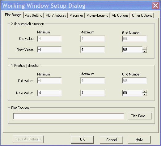
This tab brings up the following window and defines the computation range of
the model and the grid number for each axis direction. The plot cation can be
setup here.

Display/Simulation area setup.
There are three main sections of this tab:X-Direction range, Y-Direction range and Plot Caption. These are each discussed below.
X-Direction range: This section displays information on the range of X (Horizontal) direction. The old values are displayed here for users information. One can specify new value in the editting boxes.
Y-Direction range: This section displays information on the range of Y(Vertical) direction. The old values are displayed here for users information. One can specify new value in the editting boxes.
Plot Caption: This specifies the title of the plot displayed on the plot. The default value is the file name of the data field or from the data file if it is specified in the file. The font, style and colour of the title can be changed by clicking on the "Title Font" button.
Save As Defaults button makes some of the setup parameters on the tab to be used as the default values when the program is started next time if it is enabled.
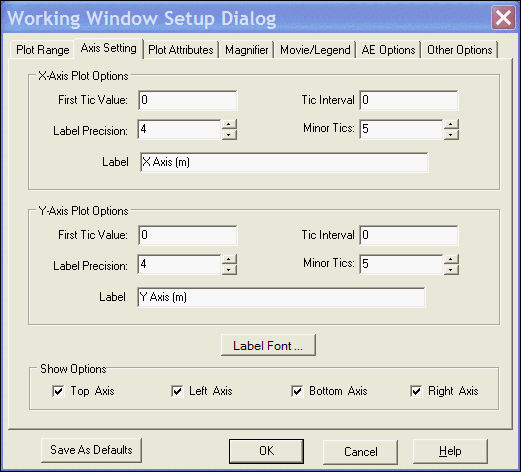
This tab allows the user to customize the axes to be displayed. It will come up with the following dialog:

Axes Setup
Axes setting: There are two axes: X-axis and Y-axis. You can specify the appearance of the axies with the following options:
First tick value and tick interval: Enables you to define what value the first tick is on the section and the interval between major ticks. When the tick interval is set to 0, as in the figure above, the program will automatically tick and label the axes with the most appropriate values.
Label precision: This defines how many decimal places you wish displayed.
Minor ticks: Allows the user to define how many minor ticks are places between the major ticks.
Label: You can specify the descriptions for the trace axis and the time axis. The default description for the X- axis is "X Axis (m)' and the one for the Y- axis is "Y Axis (m)''. The font, style and colour of the labels can be changed by clicking on the "Label Font ..." button.
Show options: These boxes are used to enable or disable the axis you wish displayed in the view window.
Selecting this tab will bring up the following window:
Plot Attribute Setup
This tab allows the user to customize various plot attributes such as Background color, Griding styles, line with and colors for fractures, stresses and displacements. Specifically:
Frame border: This option is used to change the colour and width of the border around the data displayed in the window. The backround color specifies the color outside of the data display area.
Gridding style: A regular grid can be displayed on the data in the window using this option. The line style and colour for the grid can be specified and the grid displayed on one or both of the axis.
Fratcure Geometry Lines: There are three types of fractures in the simulation: Elastic, Open and Slipping. This option allows the user to specify the line color and line width to display each type of fracture.
Stress Field Lines: There are compressive and tesile stresses to be displayed. This option allows the user to change the line width and line color to display the stress fields.
Displacement Line: This option specifies the line width and line color for display the displacement vector.
Stress/Displacement Line Length Scale: This parameter allows the user
to increase or decrease the size of the stress/displacement symbols on display.
Selecting this tab will bring up the following window:
Magnifier Setup
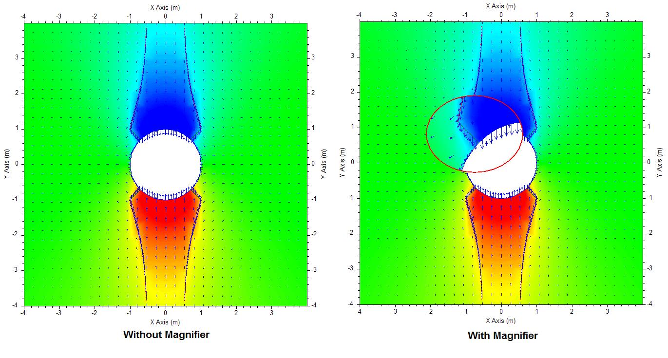
This tab specifies the Magnifier's attributes such as the shape, size, Border width, border color and magnifying scale of the magnifier.
Magnifier Geometry Type: User can select the magnifier either in rectangular or elliptical shape by selecting the coppresponding radio button.
Geometry Settings: specifies the width and height of the magnifier in pixels. The user also can choose the border line width and color for the magnifier.
Magnifying Scale: Defines how much magnification is used. The default value
is 2. The example below is on setting 2.

Selecting this tab will bring up the following window:
Movie/Legend Setup
This allows the user to specify the movie playback speed. The default speed
is an interval of 500 milliseconds. Optionally, one also can customize the legend
displayed (Default Company name, Date of the plot time, legend font and Legend
background color). One even can customize the format of the date to display.
Selecting this tab will bring up the following window:
Acoustic Emmision Options
This tab allows to customize the acoustic emission display attributes such as the AE point size, the colors for the current and previous AE events. You also can specify the water fracture display attributes here (Water shade scale and water shade color).
Selecting this tab will bring up the following window:
Model Size and Accuracy Options
Maximum Model Size - This section allows the user to specify the maximum model size for horizontal and vertical grids and the maximum number of geometry and fracture elements. Currently, the memory allocation is done before reading the model. Therefore, we have to pre-allocate memory to the model using the parameters defined here.
Accuracy - This parameter is used for automatically determing the the closed geometry paths. Sometimes, the program may hang up due to the algorithm could not find closed geometry patrhs due to the tolerance for closed path. Relaxing the accuracy usually can avoid such problem.
Material Fill Colors - This allows the user to change the background filling color of each material. To change a specified material color, you need to specify the material Order or ID number first by clicking on the updown button. To change the color, move your cursor to the Fill Color box then left mouse button click to bring up a color dialog window where you can select a color you want.